INTERNATIONAL FLUID POWER, INC.

The Experts for Hydraulic Power Units, Components, and Custom Hydraulic Systems
Slider

What Is an MPO Cable and How Does It Work?

An MPO Cable is a high-density fiber assembly designed to carry multiple optical signals through one connector. MPO means Multi-fiber Push-On, describing its compact, multi-fiber interface. Instead of using one fiber per connector, it groups several fibers into a single ferrule. This design saves rack space and simplifies high-speed network deployment. Small footprint, large capacity.

Inside an MPO Cable, individual fibers are arranged in precise rows. The connector’s guide pins help align matching fibers during connection. When the plug enters an MPO adapter, each fiber meets its corresponding position. Optical transceivers then convert electrical data into light and send it through parallel fiber channels. A 12-fiber cable may support different transmission methods, depending on the transceiver and network design. Fiber count alone does not determine total bandwidth.

In practical installations, performance depends on more than the cable label. Technicians check polarity, key orientation, connector type, and fiber mapping before deployment. They also measure insertion loss and return loss with calibrated test equipment. A clean end face matters. Dust can weaken optical signals and create intermittent faults. It is easy to treat an MPO Cable as plug-and-play, but that assumption often fails in dense data centers. The concept is straightforward. Field work is not.

This guide explains what an MPO Cable is, how its internal fibers carry data, and where its design fits within modern fiber networks. It also considers common connector configurations, polarity methods, testing practices, and installation limitations. Some details vary by manufacturer and application, so specifications should be verified before purchase or deployment.
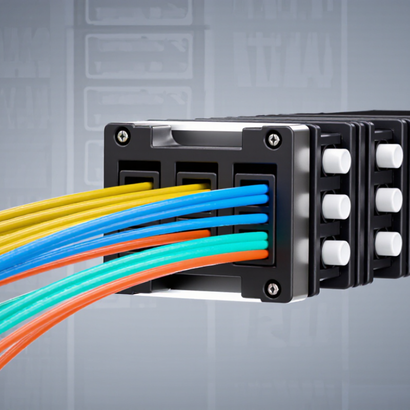
What Is an MPO Cable and How Does It Work?

MPO Cable Definition and Core Components

An MPO cable is a pre-terminated fiber assembly designed to connect many optical channels through one compact interface. MPO means Multi-fiber Push-On. Unlike a duplex fiber cable, it carries several fibers inside a single connector body. This design helps reduce installation time and cable congestion in high-density network cabinets.

Its core components include the MPO connector, fiber array, guide pins, key, housing, and protective jacket. The connector holds the fibers in a precise row. Guide pins align the mating surfaces, while the key controls the connector’s orientation. Each fiber can transmit data independently. In a typical 12-fiber assembly, six transmit and six receive fibers may support parallel communication. However, the exact use depends on the network equipment and polarity method.

The cable itself may contain single-mode or multimode fiber. Single-mode fiber suits longer links and tighter performance requirements. Multimode fiber is often practical for shorter connections inside buildings. Polarity deserves careful attention. If the transmit and receive positions do not match, the link may remain dark. That mistake is surprisingly common. Technicians should inspect end faces, verify fiber counts, and test insertion loss before deployment. A clean connector can still fail when its polarity is wrong. This is why labeling and test records matter, even for short cable runs. Some installations also require angled or flat polished ends, depending on the mating components. The specification should never be guessed.

MPO Cable Fiber Count and Duplex Connection Capacity

MPO cables use a multi-fiber connector that terminates several optical fibers in a single interface. This chart shows common MPO fiber counts and the corresponding number of duplex connections when two fibers are allocated to each duplex link.

How MPO Connectors Align Multiple Fibers

What Is an MPO Cable and How Does It Work?

An MPO cable uses one connector to align multiple optical fibers. Inside it, a precision MT ferrule holds fibers at a fixed 250-micrometer pitch. Guide pins enter matching holes and keep both ferrules positioned correctly. The connector key also controls orientation, reducing polarity errors during installation. Common versions contain 8, 12, 16, or 24 fibers. That density supports parallel transmission for high-speed links. The International Telecommunication Union reported 5.4 billion internet users in 2023. Growing connectivity increases pressure on compact network infrastructure.

Alignment sounds simple. It is not. A small amount of dust can block several channels at once. A bent guide pin may create uneven end-face contact and raise insertion loss. IEC 61754-7 and TIA-568.3-E define interface and cabling practices that help technicians verify geometry, polarity, and performance. Field testing should include inspection, cleaning, and loss measurement. Never rely on visual alignment alone.

MPO systems also reduce rack congestion. The 2024 International Energy Agency Electricity report estimates data-center electricity demand could exceed 1,000 terawatt-hours globally by 2026. Higher density can reduce cable volume and simplify airflow, but it can also hide mistakes. One reversed polarity module may interrupt an entire parallel link. I have found that clear labeling matters as much as connector precision. The hardware is advanced. Human checks remain essential.

How Signals Travel Through an MPO Link

An MPO cable is a compact fiber assembly that carries several optical channels through one connector. Inside the link, a transceiver converts electrical data into light, often around 850 nanometers for multimode fiber. The light travels through each fiber core by internal reflection. At the opposite end, photodiodes convert those pulses back into electrical signals.

An MPO link works through parallel transmission. One fiber may carry a transmit lane, while another carries a receive lane. Higher-speed systems divide data across multiple lanes, then recombine it inside the transceiver. The Ethernet Alliance 2024 roadmap tracks 400G, 800G, and 1.6T Ethernet development, making lane control increasingly important. The ITU Facts and Figures 2023 report estimated 5.4 billion people were online. That growing demand makes efficient data-center cabling practical, not optional. Still, a clean diagram can mislead. One reversed polarity, dirty end face, or unused fiber can interrupt the whole link.

Tips: Verify polarity, fiber count, connector keying, and insertion loss before installation. Use an inspection scope and cleaning tool. Test every channel after connection. Standards reduce mistakes, but they do not replace testing. A technician may expect a perfect result and still miss one weak lane. That is the uncomfortable part.

MPO Cable Types, Polarity, and Fiber Counts

An MPO cable uses one compact connector to carry multiple optical fibers.

Its name means Multi-fiber Push On. Inside, fibers sit in a precise row, not a loose bundle. Common assemblies contain 8, 12, 16, or 24 fibers. The right count depends on the transceiver and link design. A 12-fiber cable may support several duplex links, while an 8-fiber version often serves parallel optical channels. Fiber type also matters. Single-mode supports longer distances, while multimode suits shorter data-center runs.

MPO cable types include trunk, harness, and interconnect assemblies.

A trunk has MPO connectors at both ends. A harness changes one MPO connector into several duplex connectors. Interconnect cables usually connect matching MPO interfaces directly. Polarity controls how transmitted light reaches the receiving fiber. Type A keeps fiber positions straight. Type B reverses the positions. Type C reverses fiber pairs.

Small details matter here. Connector gender matters too. One side normally uses guide pins, while the mating side accepts them. A mismatch can stop the link completely.

Technicians should verify polarity before installation.

Fiber inspection and polarity testing are safer than relying on cable labels alone. Labels can be unclear. Another frequent mistake is mixing fiber counts with lane requirements. More fibers do not automatically mean higher performance. The optical modules, mapping method, and patching layout must agree.

A clean end face also matters, because one tiny contaminant can affect several channels at once. Even experienced installers should recheck the diagram. Memory is not a testing method.

Where MPO Cabling Is Used and What to Check

What Is an MPO Cable and How Does It Work?

An MPO cable is a high-density fiber assembly with multiple optical fibers inside one connector. It carries several data channels through a compact interface. In a data center, this design saves rack space and reduces cable congestion. A trunk cable may connect patch panels, switches, or server networks across short and medium distances. Breakout cables divide one MPO connection into separate duplex links. This flexibility supports parallel transmission and structured cabling upgrades.

Where MPO Cabling Is Used and What to Check

MPO cabling is common in data centers, cloud facilities, telecom rooms, and high-performance computing environments. Before installation, check fiber count, polarity, connector gender, and insertion loss. A small mismatch can stop the link. Confirm the cable type matches the transceiver and equipment port. Also inspect the key orientation and adapter alignment. Dust is a frequent problem. Even a tiny particle can weaken the optical signal. Check the required reach and bend radius, especially inside crowded cabinets. Cable labels should remain visible after installation. This simple habit can prevent hours of tracing.

Tips: Clean and inspect every connector before mating. Use an inspection scope when available. Keep unused ports capped. Test each channel with suitable optical equipment, and record the results. Do not assume a factory-made cable is perfect; handling damage can happen during delivery or installation. I have seen neat-looking links fail because polarity was checked too late. That mistake is easy to repeat. A final end-to-end test gives the network team stronger evidence before service activation.

What Is an MPO Cable and How Does It Work? - Where MPO Cabling Is Used and What to Check

Data Dimension Typical Data or Configuration How It Works or Where It Is Used What to Check
Basic Definition Multi-fiber push-on connector and cable assembly An MPO cable terminates multiple optical fibers in a single connector. It enables several transmit and receive channels to be connected at the same time. Confirm that the connector type, fiber count, and application are compatible.
Fiber Count Common configurations include 8, 12, 16, 24, 32, and 48 fibers Higher fiber counts support more parallel optical channels in a compact cable footprint. Twelve- and twenty-four-fiber assemblies are widely used in structured cabling. Check whether all fibers are active or whether some are reserved for future expansion.
Transmission Method Parallel transmission or breakout transmission Parallel links use multiple fibers simultaneously. A breakout harness can divide one multi-fiber connector into several duplex connectors for individual channels. Verify the required breakout ratio and the direction of each transmit and receive fiber.
Typical Network Roles Trunk, harness, patch, and cassette connections MPO trunks provide high-density backbone links. Harnesses connect multi-fiber ports to duplex equipment ports, while cassettes provide an organized transition between connector formats. Check connector access, bend radius, rack space, and cable-management capacity.
Common Data-Center Applications Server-to-switch, switch-to-switch, and leaf-spine links MPO cabling is used in high-density data centers where fast installation, standardized polarity, and fiber scalability are important. Match the cabling design to the transceiver interface and planned upgrade path.
Parallel-Optics Example Four transmit fibers and four receive fibers use eight fibers An eight-fiber parallel link can carry four optical lanes in each direction. This arrangement is used by several short-reach parallel-optics applications. Do not assume that every eight-fiber cable supports the same speed or optical standard.
Multimode Fiber Types OM3 and OM4 are common for short-reach data-center links Multimode fiber is often selected for short distances because it supports high-speed transmission with relatively low-cost optical components. Confirm the required fiber category, reach, wavelength, and transceiver specification.
Single-Mode Fiber Types OS2 is used for longer-reach or campus-scale links Single-mode MPO assemblies can support longer distances and higher link budgets than typical multimode installations. Check the optical budget, wavelength, connector polish, and equipment compatibility.
Connector Gender Male connectors use guide pins; female connectors have guide-pin holes Guide pins align the multi-fiber ferrules during mating. Two connectors with the same gender generally cannot be mated directly. Verify gender at every connection point, especially when using trunks, cassettes, and adapters.
Connector Keying Key-up, key-down, and other keyed orientations The key controls connector orientation and helps maintain the intended fiber position during mating and polarity management. Check the key orientation on both ends before installation.
Polarity Method Type A, Type B, and Type C polarity schemes Polarity defines how each fiber position at one end corresponds to a fiber position at the other end. Type A maintains position, Type B reverses positions, and Type C reverses fiber pairs. Use one documented polarity method throughout the link and confirm the end-to-end Tx/Rx mapping.
Fiber Alignment Precision alignment through a multi-fiber ferrule and guide-pin system The ferrule holds the fiber ends in a fixed array. Guide pins align the ferrules so that the corresponding fiber cores face each other. Inspect ferrule end faces and guide-pin condition before mating.
Insertion Loss Often specified as low-loss or standard-loss; the exact limit depends on the assembly Insertion loss is the optical power lost when light passes through the connector pair or cable assembly. Lower loss leaves more margin for the complete link. Use the measured or specified value rather than relying only on a typical range.
Return Loss Depends on fiber type, connector polish, cleanliness, and mating quality Return loss describes reflected optical power. A higher return-loss value generally indicates less reflected light. Check return-loss requirements when the equipment or optical design specifies them.
Fiber Polishing Physical-contact polish variants are selected according to the system design The polish affects how fiber end faces contact and how much optical reflection is produced at the connection. Do not mix incompatible polish types or assume that all MPO connectors have identical end-face performance.
Cable Construction Ribbon, ribbonized, or round multi-fiber cable designs Ribbon-style designs organize fibers in a flat array, while round designs can provide additional flexibility for routing in some installations. Check cable diameter, flexibility, pulling method, and compatibility with the planned pathway.
Bend Radius Must follow the cable manufacturer's minimum static and dynamic bend-radius limits Bending a cable too sharply can increase attenuation, damage the fiber, or reduce long-term reliability. Maintain the specified bend radius during pulling, routing, and service changes.
Cleaning Requirement Inspect and clean every connector end face before mating Dust and residue can increase insertion loss, create reflections, and permanently scratch the polished fiber surface. Use inspection equipment and fiber-appropriate cleaning tools; never inspect an active fiber end face directly.
Testing Visual inspection, continuity or polarity verification, and insertion-loss testing Testing confirms that fibers are connected in the intended order and that the completed link remains within its optical-loss budget. Test the installed channel, not only individual components, and retain the results for documentation.
Installation Advantage High fiber density with fewer individual patch cords A single MPO connection can replace multiple individual fiber connections, reducing cable bulk and simplifying large-scale deployment. Plan labeling and service loops carefully because one connector can carry many channels.
Main Limitation More complex polarity, gender, and fiber-position management A single incorrect key orientation, gender selection, or polarity assignment can interrupt multiple optical channels at once. Keep a complete end-to-end connection map and label both cable ends.
Note: Performance values and supported applications depend on the fiber type, connector design, transceiver specification, cable length, polarity method, and installation quality. Always verify the applicable cabling and equipment requirements before deployment.