What Is a 15kV 200A Loadbreak Junction?
A 15kv 200a Loadbreak Junction is a medium-voltage interface used to connect, divide, or extend underground distribution circuits. Its 15 kV class rating identifies the insulation level, while 200 A describes the continuous current capacity under specified conditions. The device commonly works with compatible loadbreak elbows, bushings, and insulated cable terminations.
Inside a pad-mounted transformer vault or underground enclosure, the junction may serve as a compact connection point between feeders. A technician can see several molded interfaces arranged around a grounded enclosure, with screened insulation protecting energized parts. This arrangement supports circuit sectionalizing and maintenance planning without exposing live conductors during normal operations. However, the junction is not a universal switch. Its loadbreak capability depends on the complete mating system, approved accessories, and the manufacturer’s operating instructions.
Real-world selection requires more than matching voltage and amperage. Engineers should verify fault-current ratings, insulation coordination, cable size, interface type, grounding provisions, environmental sealing, and applicable utility standards. Installation quality matters greatly. Poor torque, contamination, or an incorrectly seated elbow can create heat, tracking, or premature failure.
The name sounds simple.
Yet details decide safety.
A careful review should compare the product data sheet with the actual network design. Ratings may vary by installation altitude, temperature, duty cycle, and testing standard. Even experienced crews can overlook these conditions. For that reason, this article examines what a 15kv 200a Loadbreak Junction is, how its components function, where it fits in distribution systems, and which technical checks support dependable service.
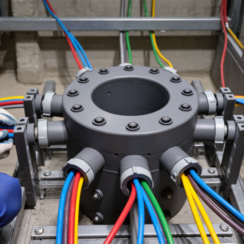
Definition and Purpose of a 15kV 200A Loadbreak Junction
A 15 kV 200 A loadbreak junction is a medium-voltage connection point for controlled feeder switching. “15 kV” describes the nominal voltage class, not guaranteed operating voltage. “200 A” indicates continuous current capacity under specified conditions. Loadbreak operation allows trained personnel to open the connection while carrying rated load current. It does not mean the junction can interrupt a short circuit. Fault interruption requires a properly rated protective device. The assembly commonly includes a dead-front insulated interface, separable connectors, shielding, and a parking position. Crews may connect feeder sections, transformer leads, or branch circuits there.
Its purpose is controlled sectionalizing during maintenance, expansion, or fault isolation. This can reduce outage areas and limit exposed work zones. DOE’s Quadrennial Energy Review reported that distribution systems account for roughly 92% of power interruptions in the United States. That figure shows why accessible sectionalizing points matter. NERC’s 2024 Long-Term Reliability Assessment projects North American peak demand to increase about 15% over the next decade. Flexible medium-voltage connections may support changing feeder loads and distributed generation. However, a junction is not an automatic reliability solution. Engineers must verify insulation coordination, fault current, grounding, temperature, altitude, and compatibility with IEEE 386 and IEEE C37.74 requirements. A common mistake is treating “15 kV, 200 A” as a universal guarantee. Ratings depend on the complete assembly and installation.
What Is a 15 kV 200 A Loadbreak Junction?
Rated electrical parameters of a medium-voltage loadbreak junction
A 15 kV 200 A loadbreak junction is a separable medium-voltage connection point designed for connecting, isolating, and switching energized distribution cables or equipment under specified load conditions. The 15 kV designation identifies the voltage class, while 200 A identifies the continuous current rating. Actual operating limits depend on the applicable standard, installation conditions, and the complete assembly.
Key Electrical Ratings and Structural Components
What Is a 15kV 200A Loadbreak Junction?
Key Electrical Ratings and Structural Components
A 15kV 200A loadbreak junction connects medium-voltage cable sections safely. The 15kV label usually indicates a 8.3/14.4kV phase-to-ground system class. The 200A value describes continuous current, not automatic fault interruption. IEEE Std 386-2016 treats these interfaces as separable, shielded connectors. That distinction matters.
Typical electrical data includes a 95kV basic impulse insulation level and a short-time fault rating near 10kA symmetrical. Exact values vary by design. A junction may also carry a 200A loadbreak rating, but this should not be assumed from the voltage label alone. IEEE Std 592-2007 emphasizes shielding and interface control for high-voltage separable connectors. CIGRE reliability studies repeatedly identify moisture, contamination, and poor installation as major insulation risks. Numbers help, but field conditions decide performance.
The structure usually includes a molded epoxy or rubber body, a conductive insert, and a loadbreak probe. A semiconductive outer shield controls electric stress. Grounding eyes and a drain wire connect the shield to the system ground. Some designs include parking provisions for an elbow connector. The mating interface must remain clean and fully engaged. Small gaps are dangerous. In practice, I would inspect torque, cable stripping dimensions, and shield continuity before energizing. A tidy enclosure can still hide a weak interface. The product drawing and certified test report should confirm continuous current, withstand voltage, impulse level, and fault-duty limits. Without those documents, calling it “15kV 200A” is only a partial description.
How a Loadbreak Junction Operates in Medium-Voltage Systems
A 15kV 200A loadbreak junction connects medium-voltage cables inside a compact, shielded enclosure. The 15kV rating identifies its voltage class, while 200A usually describes continuous current capacity. It is not simply a larger terminal block. Its insulation, interfaces, and grounding provisions must withstand electrical stress, moisture, and fault conditions.
The operating process begins with an approved loadbreak elbow and an insulated operating tool. A trained technician positions the elbow on the junction interface, following the equipment procedure and required clearances. As the elbow engages, its internal probe and arc-control design interrupt the circuit under permitted load conditions. The surrounding shield helps control the electric field and reduces accidental contact exposure. It feels mechanical, but the timing is electrical.
After connection, the elbow is fully seated and secured. A visible ground point may also be checked, depending on the system design. The 200A value is often misunderstood; it does not authorize every switching event or fault current. Cable size, system configuration, temperature, and local rules still matter. Poor torque or contamination can create hot spots later. That detail is easy to miss.
Qualified personnel should verify voltage absence when required, inspect interfaces, and use rated protective equipment. A junction is not automatically a complete switch. Its actual loadbreak function depends on the compatible separable connector and its tested operating limits. Reduced attention here can turn a routine change into a serious failure.
Common Installation Methods and Compatible Equipment
What Is a 15kV 200A Loadbreak Junction?
A 15kV 200A loadbreak junction connects medium-voltage underground cables at a common point. It usually includes multiple loadbreak interfaces inside a sealed, insulated enclosure. The 15kV rating identifies its voltage class, while 200A indicates continuous current capacity under specified conditions. It is not simply a cable connector. Its housing, interfaces, and grounding path must work together.
Common installation methods include direct mounting on pad-mounted transformers, switchgear, or sectionalizing cabinets. Installers may also place the junction inside a vault or on a compact steel bracket. Cable routing should avoid sharp bends, standing water, and unnecessary mechanical stress. A firm support matters. Small movement can strain the cable interface over time.
Compatible equipment typically includes 15kV-class loadbreak elbows, bushing inserts, feed-through devices, parking stands, and grounding accessories. Cable size, conductor material, insulation diameter, and interface type must match the junction’s technical data. A 200A rating alone does not confirm compatibility. Field crews should inspect each mating surface, clean it carefully, and apply approved lubricant where specified. The circuit should be de-energized unless the equipment is specifically rated and procedures are followed for loadbreak operation.
One detail is easy to miss: phase spacing and cable bending space. Crowded compartments make testing and maintenance harder. I have seen installation plans that fit electrically but fail physically. A final torque check, grounding inspection, and phase identification can prevent that avoidable problem.
Safety Requirements, Maintenance, and Typical Applications
A 15kV 200A loadbreak junction connects medium-voltage cables and equipment inside an insulated distribution system. It supports controlled switching when paired with properly rated loadbreak components. Typical installations include underground feeders, transformer connections, pad-mounted gear, and temporary network extensions. The 15kV rating does not make every nearby component safe. The complete system must match the voltage, current, fault-duty, and interface requirements.
Only qualified electrical workers should operate or service this equipment. They must review the switching plan, isolate all possible sources, test for absence of voltage, and apply approved grounds. Rated gloves, face protection, arc-rated clothing, and insulated tools remain essential. Loadbreak operation requires the correct operating sequence and firm movement. Hesitation can create an arc. IEEE 386 practices may apply, but the equipment documentation and local regulations control the job.
Maintenance starts with a de-energized visual inspection. Look for cracked insulation, tracking marks, loose hardware, moisture, damaged cable jackets, and distorted sealing parts. Clean interfaces with approved materials, not sharp tools or unverified solvents. Check torque values against the installation record. Thermal scanning can reveal unusual heating during service, but it cannot replace physical inspection. A small defect may hide beneath dirt. Field judgment still matters. Even experienced crews can miss contamination after heavy rain, so inspection intervals should reflect weather, switching frequency, and the consequences of failure.
